

top of page

How to Choose an Ultra High Temperature Servo Motor?

Choosing an Ultra High Temperature Servo Motor is not a matter of reading one temperature rating. Heat affects insulation, magnets, bearings, lubricant, feedback devices, and cable life. A motor may tolerate a hot winding while its encoder or connector becomes the weak point. That distinction matters in a furnace line, test chamber, or compact machine where cooling air is limited.

Dr. Robert Lorenz is a recognized researcher in electric drives and motion control. However, no source text was provided to verify a direct quotation from him about ultra-high-temperature servo motors. Rather than inventing words and attributing them to an expert, this guide focuses on verifiable selection criteria. Its practical rule is simple: “Treat temperature as a system limit, not just a motor rating.” That is an editorial principle, not a quotation from Dr. Lorenz.

The sections ahead examine ambient and winding temperatures, continuous versus peak duty, torque derating, insulation class, encoder limits, and cooling options. They also show what to ask suppliers: the permitted temperature at each component, the test conditions behind the rating, and expected service life under your real load cycle. Check the details against the machine, not only the catalogue. A motor beside a glowing workpiece faces different conditions from one inside a sealed cabinet. Even careful sizing can miss a weak point. That is worth admitting before purchase.
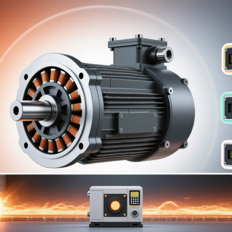
How to Choose an Ultra High Temperature Servo Motor?

Define the Required Temperature Range and Operating Conditions

Before selecting an ultra-high-temperature servo motor, define the temperature it must withstand continuously—not just the hottest brief spike. Record ambient air, nearby radiant heat, enclosure temperature, and heat conducted through the mounting surface. A motor beside a furnace may face very different conditions from one inside a heated cabinet. Measure at the motor location during a full production cycle, if possible.

Separate ambient temperature from winding temperature.

IEC 60085 assigns thermal classes of 155°C for Class F and 180°C for Class H insulation systems. These are insulation-system temperature limits, not permitted ambient temperatures. The IEC 60034-1 motor standard also treats operating conditions and temperature rise as selection factors. Ask the supplier for the motor’s rated ambient range, winding-temperature limits, and derating curve; a high insulation class alone does not prove the whole servo is suitable.

Operating details matter.

Note peak and continuous torque, speed, duty cycle, cooling airflow, and the temperature of cables, encoder, seals, and feedback devices. A motor may tolerate heat but lose performance when a sealed enclosure traps it. Include start-stop frequency, too. Small oversight, big consequence. I would also leave margin above the measured temperature: real equipment often runs hotter after filters clog or airflow changes. Recheck the estimate against actual operating data before finalizing the specification.

Identify the Servo Motor’s Core Performance Requirements

How to Choose an Ultra High Temperature Servo Motor?

Identify the Servo Motor’s Core Performance Requirements

Start with the actual temperature around the motor, not just the oven or process setting. A motor mounted near a hot chamber may face radiant heat, poor airflow, and short bursts of even higher temperatures. Measure at the motor. Record both steady-state conditions and peak temperatures during a full operating cycle.

Next, define the motion task in measurable terms: required torque, speed, acceleration, positioning accuracy, and duty cycle. A conveyor indexing every few seconds creates a different thermal load than a slow valve that moves occasionally. Include the load’s inertia and any brief overloads. Heat changes everything. At elevated temperatures, winding resistance can rise, reducing available torque; insulation, bearings, seals, and feedback devices also need suitable temperature ratings.

Specify whether the rating refers to ambient temperature, winding temperature, or another measurement point. These figures are not interchangeable, and overlooking that distinction can lead to an undersized system. Check how the motor will reject heat, whether cooling is available, and how cables and connectors tolerate the installation environment. A cautious margin is useful, though excessive oversizing can affect cost and control response. Requirements are rarely perfect on the first pass; validate them against measured operating data before final selection.

Compare Insulation, Cooling, and High-Temperature Materials

How to Choose an Ultra High Temperature Servo Motor?

Insulation class is a starting point, not a guarantee of safe operation. IEC 60034-1 lists thermal classes B, F, and H at 130°C, 155°C, and 180°C. These values describe insulation-system thermal classes, not the motor’s allowed ambient temperature. Check the supplier’s test data for winding hot spots under your real speed, torque, and duty cycle. Check the winding hotspot. A short overload can raise local temperatures beyond what an average reading reveals.

Cooling changes the result. A fin-cooled motor may struggle inside a hot, enclosed machine, while liquid cooling depends on stable flow and clean channels. Ask for temperature-rise data at the specified coolant temperature and flow rate. Compare continuous and peak torque ratings under those conditions; peak figures alone can mislead. Small detail, big risk: blocked airflow or a warm coolant return can shrink the thermal margin.

Review every heat-sensitive component, not just the winding insulation. Slot liners, impregnation resin, lead wires, connectors, encoder, bearings, and lubricant must all tolerate the actual temperature. Magnet grades also differ in resistance to irreversible demagnetization. Request material limits and test reports, then compare them with measured motor temperatures. I would question any selection based only on a “high-temperature” label; the weakest component often sets the practical limit.

Check Compatibility with the Drive, Encoder, and Load

An ultra-high-temperature servo motor is only useful when its drive, encoder, and load remain compatible under real operating conditions. The U.S. Department of Energy’s Improving Motor and Drive System Performance sourcebook reports that motor-driven systems use about 68% of electricity in U.S. manufacturing. That makes system-level efficiency more than a motor-only question. Check the drive’s continuous and peak current, voltage, and thermal derating against the motor’s ratings at the actual ambient temperature. IEC 60034-1 defines insulation thermal classes, including F at 155°C and H at 180°C; these are insulation limits, not permitted ambient temperatures.

Match the feedback device to the drive’s supported signal type, voltage, and resolution. Confirm that the encoder and its cable can tolerate heat near the motor, or consider a remote-mounted feedback device where the design allows it. Then compare the load’s inertia, peak torque, and duty cycle with the motor-drive combination. A large inertia mismatch can cause sluggish starts or unstable motion. One easy-to-miss detail: high-temperature ratings may depend on cooling and installation conditions, so check the test conditions behind each rating.

Tips: Verify compatibility using the actual cable length, ambient temperature, and load profile. Ask for thermal derating curves and feedback limits, not just headline ratings. It is tempting to treat a listed maximum temperature as a safe operating target; pause and check what that number actually describes.

Evaluate Testing, Protection, and Maintenance Requirements

For an ultra-high-temperature servo motor, test the complete assembly, not only the winding. Run it in a thermal chamber under the real duty cycle, including repeated starts, peak torque, and rapid stops. Record winding, bearing, and encoder temperatures while checking speed stability and torque output. IEC 60085 defines thermal insulation classes F and H at 155°C and 180°C, respectively. These are insulation-system limits, not recommended operating temperatures for every motor component. A hot winding can coexist with an encoder or bearing that is already overheating.

Tips: Ask for test records showing ambient temperature, load, duration, and sensor locations. Check protection settings against the motor’s actual duty cycle. Thermal sensors, overload protection, and suitable high-temperature grease can help, but none replaces a validated temperature rating. IEEE 43-2013 provides established methods for insulation-resistance testing; use consistent test conditions so readings can be compared over time.

Maintenance should track trends, not just failures. Log bearing vibration, insulation resistance, and temperature after stable operating periods. Inspect seals and cable insulation for hardening or cracks; small changes matter. I would still question any rating without a clear test setup. It is easy to miss a weak point. A maintenance interval copied from a cooler application may not fit a furnace line, especially when dust and frequent starts are involved.

How to Choose an Ultra High Temperature Servo Motor? - Evaluate Testing, Protection, and Maintenance Requirements

Selection Dimension What to Evaluate Practical Selection Guide Evidence to Request
Maximum ambient temperature Temperature around the motor during normal operation, startup, shutdown, and foreseeable process upsets. Specify the measured temperature at the motor location, not just the furnace or process temperature. Confirm the motor’s permitted ambient range and output derating at the actual operating temperature; there is no universal “ultra high temperature” rating. A temperature-versus-torque or temperature-versus-current curve, plus documented operating limits for the complete motor assembly.
Required torque and speed Continuous torque, peak torque, speed range, duty cycle, acceleration, and load inertia at temperature. Check the torque-speed curve after thermal derating. Verify that peak torque duration and repetition rate are allowed, and include gearbox, coupling, and process-load effects in the sizing calculation. Application sizing report and torque-speed curves for the stated cooling method and ambient conditions.
Insulation and winding temperature Insulation-system thermal class, winding temperature rise, hot-spot limits, and effects of drive-generated voltage stress. Ask for the declared insulation-system class and the conditions behind it. A temperature class is not, by itself, a guarantee that the complete motor can operate at that ambient temperature. Thermal test records and insulation-system documentation; confirm applicable IEC 60034 requirements with the supplier.
Temperature and endurance testing Whether tests reproduce the actual ambient temperature, load profile, cooling arrangement, and operating duration. Prefer a representative loaded thermal run that continues until temperatures stabilize, followed by inspection and functional checks. Test duration and acceptance criteria should match the application risk and be agreed in advance. Test setup, calibrated sensor locations, ambient and winding-temperature records, load profile, run duration, and pass/fail criteria.
Feedback device and position accuracy Encoder or resolver operating-temperature limit, accuracy, repeatability, and cable or signal-interface limits. Check the feedback device’s own temperature rating separately from the motor rating. If the sensor cannot tolerate the motor environment, consider a validated remote or thermally isolated arrangement where the control system permits it. Feedback-device datasheet, accuracy specification over temperature, and evidence of operation with the selected drive.
Cables, connectors, and seals Continuous and short-term temperature limits, chemical compatibility, flexibility, strain relief, and connector sealing. Rate every exposed component for the temperature at its installed location. A high-temperature motor winding does not make standard connectors or cables suitable for the same environment. Cable and connector temperature ratings, material compatibility information, and assembly-level environmental test details.
Ingress and contamination protection Dust, water, oil, abrasive particles, corrosive vapors, and cleaning methods in the installation area. Choose an enclosure and sealing arrangement for the actual exposure. Verify the stated IP code against IEC 60529 and remember that an IP rating does not establish resistance to every chemical, hot gas, or cleaning process. Declared IP rating and test basis, materials list, and any application-specific chemical or dust compatibility data.
Cooling and heat path Natural or forced cooling, air temperature, airflow availability, mounting orientation, and heat conducted from nearby equipment. Confirm that the specified cooling method remains available at the installation temperature. Prevent radiant heat and hot process structures from exceeding component limits; do not assume airflow alone will provide adequate cooling. Installation drawing, cooling requirements, derating data, and thermal assessment for the proposed mounting arrangement.
Protection and monitoring Winding temperature sensors, drive overcurrent protection, overload response, feedback fault detection, and safe shutdown behavior. Confirm sensor type, placement, trip threshold, response time, and drive compatibility. Set protection using the motor and drive documentation; avoid bypassing thermal or electrical safeguards. Protection circuit description, alarm and trip settings, sensor wiring details, and fault-response test results.
Maintenance and service access Inspection access, bearing and lubricant requirements, contamination buildup, cable condition, and availability of replacement components. Use the manufacturer’s service intervals and lubricant specifications for the actual temperature and duty. Set inspection frequency from operating conditions and condition-monitoring results rather than assuming a universal interval. Maintenance schedule, bearing and lubricant limits, inspection checklist, and recommended spare-parts list.
Commissioning and acceptance Correct rotation, feedback polarity, current limits, thermal protection, vibration, and performance under the intended load. Define acceptance checks before installation. Commission at a controlled load, verify protection functions, record baseline temperatures and vibration, and follow site safety procedures. Signed commissioning record with parameter settings, measured temperatures, alarms tested, and agreed acceptance limits.

Note: Temperature limits and test procedures are application- and design-specific. Confirm ratings for the complete motor, feedback device, cables, connectors, and protection system using the supplier’s documentation and the applicable standards.

bottom of page