

How to Choose the Right PCB Control Board in 2026?
Choosing the right Pcb Control Board in 2026 requires more than comparing prices or counting input channels. The board must match the machine, environment, production scale, and maintenance strategy. A dusty factory floor demands different protection from a clean laboratory. Heat, vibration, electrical noise, connector quality, and firmware support can determine whether a system runs reliably for years.
Market pressure is also reshaping the decision. The World Semiconductor Trade Statistics (WSTS) projected global semiconductor sales above 700 billion U.S. dollars in 2025, showing continued demand for intelligent electronic systems. IPC’s Global Sentiment of the Electronics Industry reports have repeatedly identified supply availability, labor costs, and component volatility as major industry concerns. IPC technology roadmaps also emphasize higher integration, miniaturization, signal integrity, and long-term product reliability. These trends make board selection a technical and purchasing decision.
A suitable Pcb Control Board should support required voltage levels, communication protocols, processing performance, expansion options, and safety requirements. Verify lifecycle status before approving the design. A board may perform perfectly on a workbench, yet fail beside a motor or heater. That mistake is common. It is also costly. Engineers should review datasheets, thermal measurements, EMC test results, certification documents, and supplier traceability. Independent evidence matters more than attractive specifications. However, no report can replace application testing. A practical evaluation should include real loads, startup cycles, temperature changes, and fault recovery. The perfect board may not exist. The best choice is usually the one that balances performance, reliability, availability, serviceability, and future redesign risk.
What Is a PCB Control Board and What Does It Control?
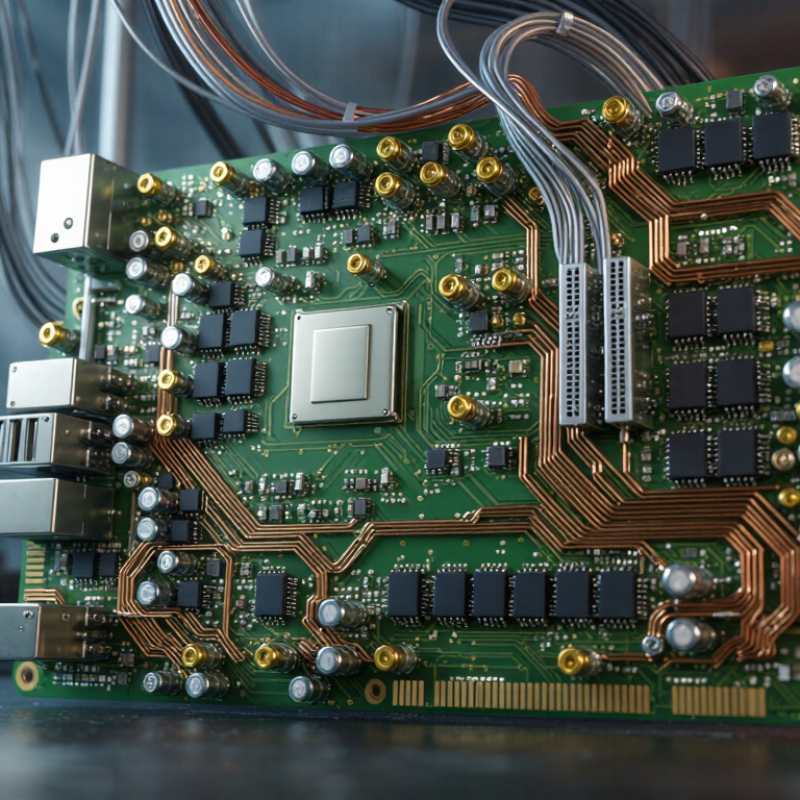
A PCB control board is the decision center inside electronic equipment. It receives information from sensors, switches, or communication lines. Then, its processor interprets that information and sends commands to motors, valves, displays, relays, or power circuits. In a factory cabinet, it may open a valve after detecting pressure changes. In a vehicle, it may regulate temperature, lighting, and safety signals.
The board does more than connect components. Its firmware defines timing, logic, and fault responses. Its power section distributes stable voltage. Its communication circuits exchange data with other controllers. WSTS reported that global semiconductor sales reached 626.9 billion dollars in 2024, growing 19.1 percent year over year. That growth reflects rising electronic complexity, but it does not guarantee reliable control design. A faster processor cannot repair poor grounding or weak thermal planning.
When choosing a control board in 2026, evaluate the actual load, operating temperature, input noise, response time, and required interfaces. IPC industry research continues to identify supply-chain pressure, skilled-labor shortages, and quality consistency as major electronics challenges. These risks affect component availability and production testing. A board that works in a quiet laboratory may fail beside an inverter. That assumption deserves testing. Leave room for diagnostics, isolation, and future firmware changes. I would also question unnecessary processing power. It often increases heat, cost, and software risk without improving control.
Which Application Requirements Should the Board Support?
How to Choose the Right PCB Control Board in 2026?
The board should match the application before it matches the enclosure. For electric mobility, the IEA reports that global electric car sales exceeded 14 million in 2023. That growth raises demand for boards supporting CAN or Ethernet, isolated power, battery monitoring, and precise thermal sensing. Industrial equipment needs different priorities. IEC 61131-3 compatibility, deterministic timing, protected inputs, and reliable operation near motors matter more than maximum processing speed.
Check the operating environment carefully. Will the board face vibration, dust, condensation, or a wide temperature range? IPC’s 2024 technology roadmap highlights miniaturization, higher power density, and thermal management as continuing industry pressures. Therefore, review creepage distance, heat paths, connector retention, and enclosure airflow instead of trusting a laboratory specification. Small details fail first.
Connectivity also creates responsibility. NIST guidance on platform firmware resilience supports secure boot, signed updates, access control, and recovery planning for connected controllers. The board should support these functions without consuming excessive memory or slowing real-time control.
Serviceability deserves attention too. The Global E-waste Monitor 2024 recorded 62 million tonnes of electronic waste in 2022, with projections reaching 82 million tonnes by 2030. A replaceable module, accessible test points, and documented firmware can extend useful life. I have found that “future-proof” designs often become oversized and expensive. That judgment can be wrong. Validate the actual sensors, loads, safety class, and maintenance schedule before selecting the processor.
How to Compare Processing Power, Interfaces, and Connectivity
How to Choose the Right PCB Control Board in 2026?
Processing power should match the workload, not the marketing label. A single-core board may control relays reliably, while vision, local analytics, and encryption need multiple cores and more memory. IoT Analytics reported 18.5 billion connected IoT devices in 2024, with further growth expected in 2025. That growth increases local processing demands. However, more computing power also raises heat, power consumption, and firmware complexity. Measure startup time, response latency, and sustained temperature with your actual sensors attached. Peak benchmark scores can mislead.
Interfaces often decide whether a board survives real installation work. Count digital inputs, analog channels, serial ports, USB, Ethernet, and fieldbus support. Check voltage levels and isolation carefully. One missing isolated port can force an expensive redesign. For connectivity, compare bandwidth, range, latency, antenna placement, and recovery after signal loss. GSMA Intelligence projected more than two billion 5G connections worldwide by the end of 2025, but cellular is not automatically the best choice. A factory cabinet may favor Ethernet or a fieldbus, while a remote meter may need cellular or low-power wide-area networking. Wired links feel boring. They often behave better.
Leave processing headroom of roughly 25 percent for future firmware changes. That figure is practical, not universal. Some projects need more. Test the board inside its enclosure, near motors, and during network interruptions. I once trusted a clean laboratory connection too quickly; field interference exposed the mistake. Reviewers should challenge their own assumptions, especially when comparing interface counts without checking simultaneous use.
How to Evaluate Power, Safety, and Environmental Performance
When selecting a PCB control board in 2026, start with its actual electrical workload, not its advertised peak rating. A motor controller may draw 8 amperes continuously, while startup demand briefly reaches 22 amperes. Check both figures against copper width, connector ratings, thermal paths, and fuse coordination. Leave practical headroom. I have seen stable prototypes fail after enclosure assembly because airflow disappeared.
Safety needs testable evidence. Look for controlled separation between high and low voltage areas, suitable insulation, touch-safe terminals, and protection against reverse polarity and overcurrent. Review creepage and clearance for the intended voltage, pollution level, and installation environment. Ask for test reports, revision records, and fault-response data. Paper compliance alone is not enough. A board that passes a bench test may behave differently after dust, vibration, or repeated switching.
Environmental performance includes temperature, humidity, vibration, corrosion, and service life. Compare the specified operating range with real conditions inside the enclosure, where heat can rise sharply near relays or power devices. Inspect conformal coating requirements, connector sealing, and material flammability documentation. For outdoor equipment, condensation deserves attention. It is often underestimated. Choose diagnostic features that record temperature, voltage, and fault events, then verify them during pilot testing. I would also question optimistic lifetime estimates, especially when cooling depends on a fan that may stop.
How to Choose the Right PCB Control Board in 2026?
Reference benchmarks for evaluating power, safety, and environmental performance during early PCB control-board selection.
The 90% power-efficiency value is a practical high-efficiency design target. The 60 V DC safety value reflects the commonly used SELV threshold in IEC 62368-1 applications. The 125°C environmental span represents a reference operating range from −40°C to +85°C; actual requirements depend on the installation environment and applicable standards.
How to Verify Compatibility, Reliability, and Future Scalability
How to Choose the Right PCB Control Board in 2026?
Compatibility is more than matching a connector. Check the board’s operating voltage, current peaks, mounting holes, dimensions, communication protocols, and firmware requirements. Measure the enclosure before ordering. A two-millimeter mistake can stop installation. Review pin assignments carefully, especially when power and signal pins look similar. Request a complete datasheet, revision history, and sample test report from the supplier.
Reliability needs evidence, not attractive specifications. Look for thermal cycling data, vibration testing, humidity resistance, and protection against electrical surges. Confirm the rated temperature range matches the real enclosure environment. A board beside a motor may experience heat and noise that laboratory figures do not show. Prefer traceable component records and documented quality procedures. I have seen projects focus on processor speed while ignoring connector wear. That decision often creates expensive maintenance later.
Tips:
Test one board in the complete system before placing a large order. Check startup behavior, standby consumption, reset recovery, and communication stability. Ask how long firmware updates and replacement components will remain available. A scalable board should provide spare input/output capacity, accessible debugging points, and upgradeable memory. Still, future-proofing is never perfect. Technology changes faster than purchasing plans. Recheck the supplier’s lifecycle statement every year, and record every assumption before approval.
How to Choose the Right PCB Control Board in 2026? - How to Verify Compatibility, Reliability, and Future Scalability
| Evaluation Dimension | Basic Embedded Control Board | Industrial Control Board | Connected IoT Control Board | Safety-Critical Control Board |
|---|---|---|---|---|
| Best-Fit Application | Simple displays, small instruments, consumer equipment, and low-duty-cycle automation. | Continuous-duty machinery, motor control, process equipment, and factory automation. | Remote monitoring, distributed sensors, energy management, and connected equipment. | Equipment requiring documented risk controls, fault handling, and a defined safety lifecycle. |
| Typical Supply Architecture | Single regulated DC rail, commonly 5 V or 12 V input with local 3.3 V logic regulation. | Protected 9–36 V DC input, reverse-polarity protection, surge protection, and monitored power rails. | Protected DC input with separate power domains for processing, radio, sensors, and backup power. | Redundant or closely monitored power paths where required by the system hazard analysis. |
| Processor and Memory Planning | Microcontroller with sufficient flash, RAM, timers, ADC channels, and at least 20% spare capacity. | Industrial-grade microcontroller or processor with watchdogs, error detection, and at least 30% spare capacity. | Processor with secure boot capability, encrypted storage support, communications acceleration, and memory headroom for updates. | Processor architecture selected for diagnostic coverage, deterministic behavior, and independent fault response. |
| Recommended Communication Interfaces | UART, I²C, SPI, GPIO, and USB where required by peripherals. | CAN or CAN FD, RS-485, Ethernet, isolated digital I/O, and service interfaces. | Ethernet, Wi-Fi or cellular connectivity, MQTT or HTTPS support, UART, SPI, and low-power sensor interfaces. | Deterministic wired interfaces, redundant communication paths where necessary, and isolated service access. |
| Electrical Compatibility Checks | Confirm logic voltage levels, connector pinout, current consumption, clock requirements, and boot configuration. | Confirm input range, inrush current, load-dump exposure, grounding method, isolation voltage, and transient protection. | Confirm antenna or radio layout requirements, peak transmission current, power sequencing, and electromagnetic compatibility. | Confirm safe-state behavior, isolation boundaries, fault containment, diagnostic inputs, and controlled shutdown behavior. |
| Operating Temperature Reference | Conditional Common design range: 0 to 70 °C. Wider ranges require component and enclosure verification. | Recommended Common industrial target: −40 to 85 °C, subject to component ratings and thermal testing. | Conditional Common target: −20 to 70 °C; radio performance and battery behavior must be checked across the range. | Recommended Temperature limits must be established through documented analysis and qualification testing. |
| EMC and Immunity Verification | Evaluate radiated and conducted emissions for the final enclosure and cable arrangement. | Plan immunity and emissions testing using applicable IEC 61000-4 test methods and the target product standard. | Test radiated emissions, conducted emissions, electrostatic discharge, radiated immunity, and radio coexistence. | Use a documented verification plan covering emissions, immunity, grounding, shielding, and fault conditions. |
| PCB Assembly and Inspection | Automated optical inspection and functional testing are generally suitable for moderate-complexity assemblies. | Use controlled assembly processes, automated optical inspection, boundary scan where applicable, and functional test fixtures. | Include RF inspection, antenna clearance checks, programming verification, and communication testing. | Use traceable manufacturing records, controlled rework, electrical safety tests, and documented acceptance criteria. |
| Reliability Evidence to Request | Datasheets, revision history, production test coverage, and evidence of component availability. | Environmental test reports, thermal analysis, vibration testing, EMC results, failure-rate data, and change-control records. | Wireless certification evidence, security update policy, connectivity test results, and long-duration communication testing. | Requirements traceability, hazard analysis, verification records, diagnostic coverage, and independent review evidence. |
| Software and Firmware Support | Stable toolchain, documented bootloader, source-code access or escrow, and reproducible production firmware. | Version-controlled firmware, watchdog recovery, fault logs, field-service tools, and controlled update procedures. | Secure boot, signed firmware updates, vulnerability response process, device identity management, and rollback capability. | Documented lifecycle process, controlled configuration management, deterministic timing analysis, and verified safety functions. |
| Future Scalability | Moderate Reserve unused GPIO, memory, connector positions, and regulator capacity for foreseeable features. | High Provide expansion headers, modular communications, spare I/O, thermal margin, and a defined board-revision strategy. | High Reserve processing, storage, network bandwidth, security resources, and remote-update capacity. | Controlled Any expansion must preserve the approved safety architecture and undergo impact assessment. |
| Lifecycle and Availability Checks | Confirm a minimum product life aligned with the equipment life and identify second-source components. | Request a product-change notification process, last-time-buy policy, component lifecycle data, and redesign support. | Confirm long-term availability of processors, memory, radio modules, cloud services, and security maintenance. | Require documented configuration control, component traceability, approved substitutions, and long-term verification support. |
| Acceptance Recommendation | Suitable Choose when environmental stress, connectivity, and expansion requirements are limited. | Suitable Choose when continuous operation, electrical noise, temperature variation, and maintainability are important. | Suitable Choose when secure remote access, telemetry, and upgradeability are core requirements. | Suitable with Formal Review Choose only when the board supports the required safety process and verification evidence. |